⚒️ Assembly Guide
Assembling & soldering your new CutieCat!
Assembly video coming by Sep 10 2024.
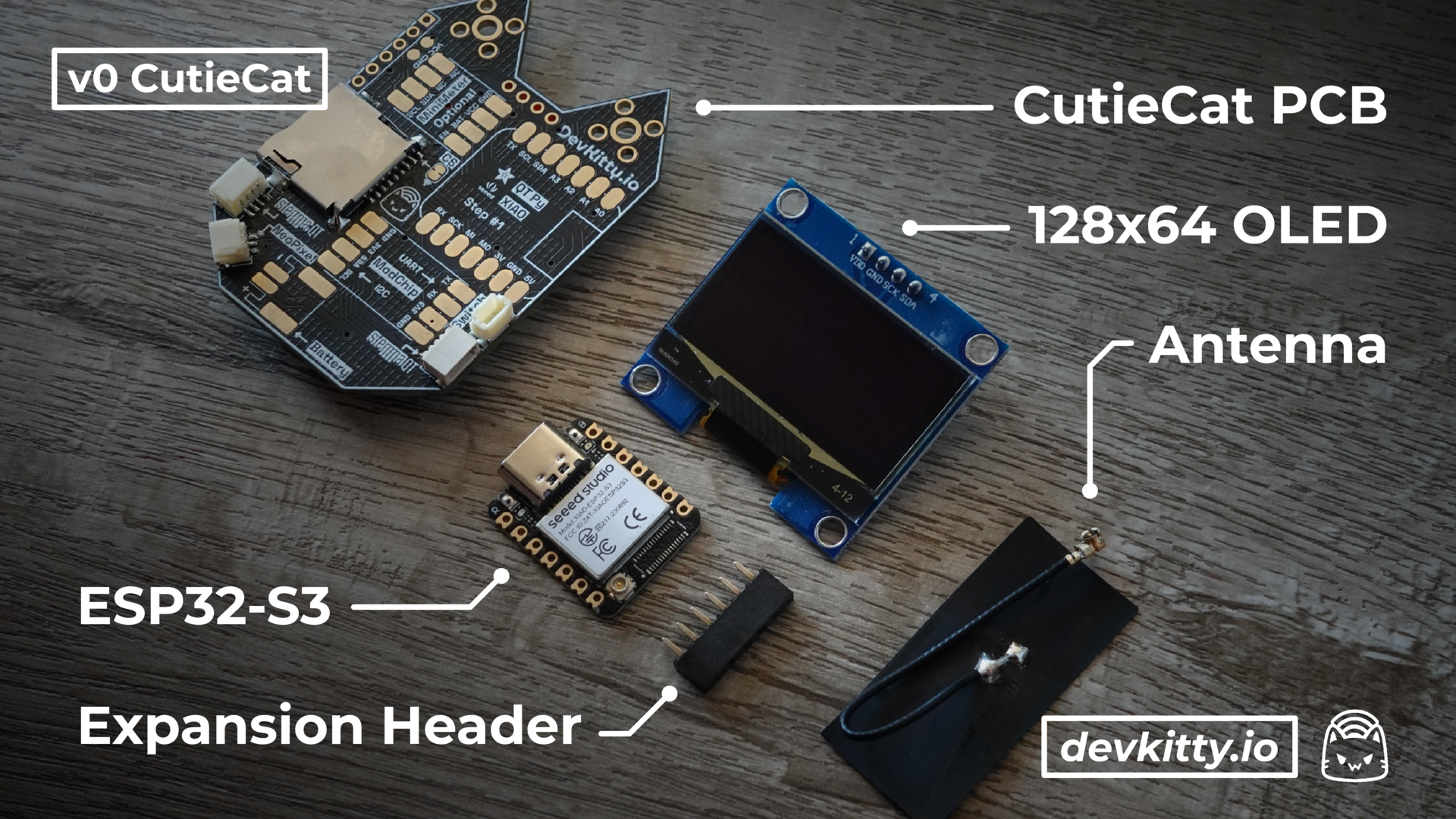
⚙ Parts
| Part | Description |
|---|---|
| Microcontroller | ESP32-S3 WiFi & Bluetooth MCU |
| Screen | 128x64px SH1106 OLED Display |
| Pin Header | 6 Pin Breakout for CutieCat Add-ons |
| Antenna (Patch) | Omni Antenna |
| Antenna (External) | Long-range Antenna |
Learn more about component selection on our hardware guide.
🗒 Steps
1. Place the ESP32
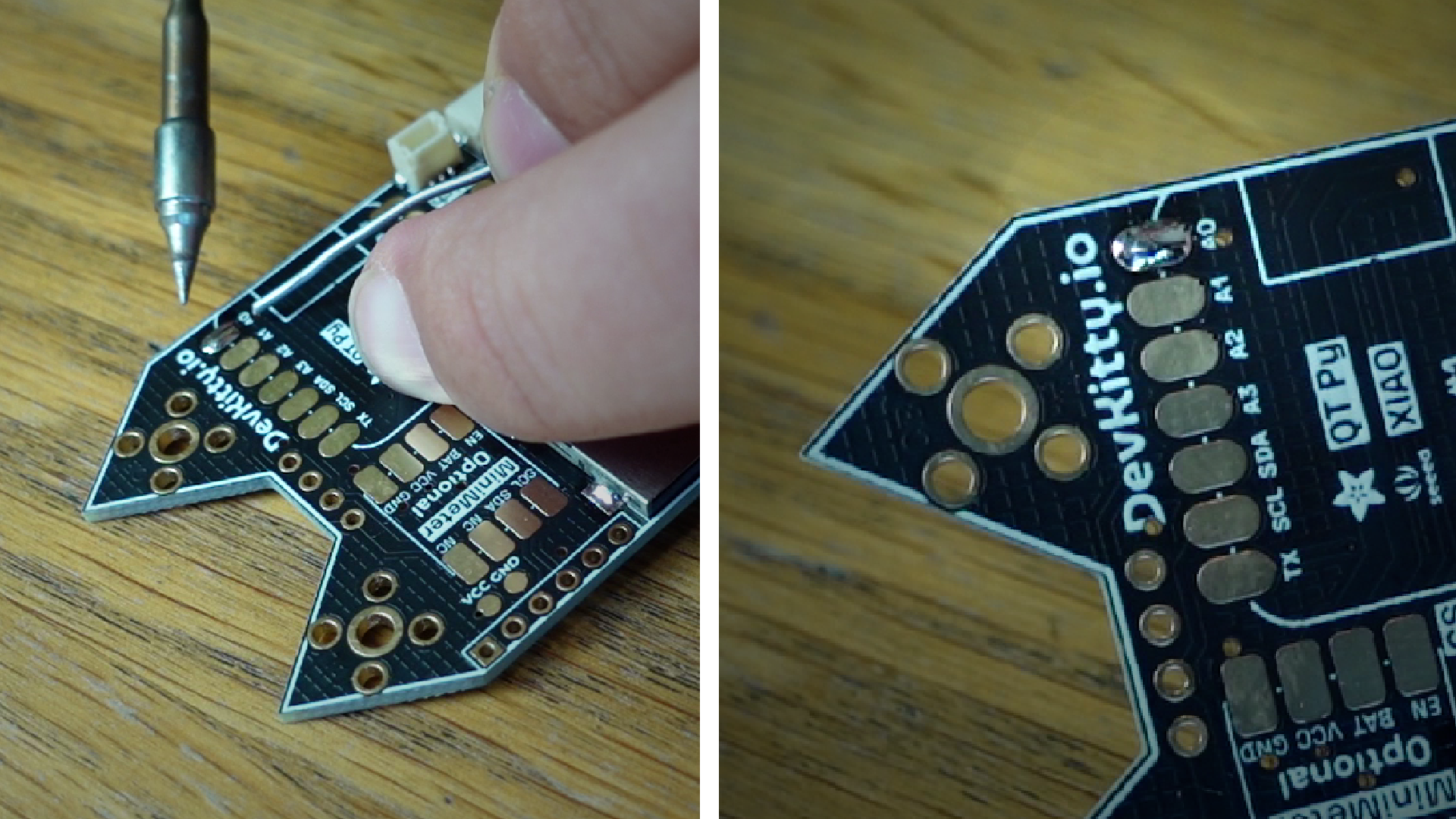
a. Melt a tack of solder onto the top right pad.
b. Reheat the blob and place the microcontroller!
- Start by melting a small “tack” of solder to one of the CutieCat microcontroller pads. This will help us place the ESP32 before committing.
- Center the ESP32 on the microcontroller footprint.
- Reheat the tack of solder until it melts, while pressing down the ESP32. Don’t worry about how the first joint looks!
- Let the solder cool! If you need to readjust the microcontroller, simply reheat the joint.
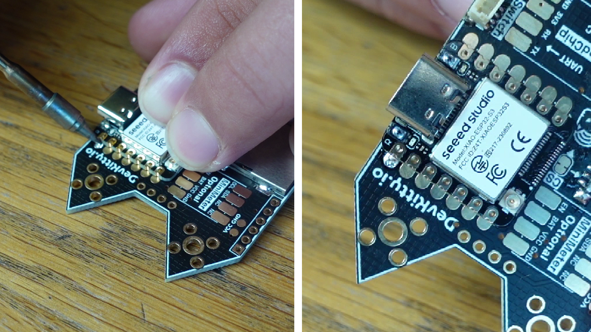
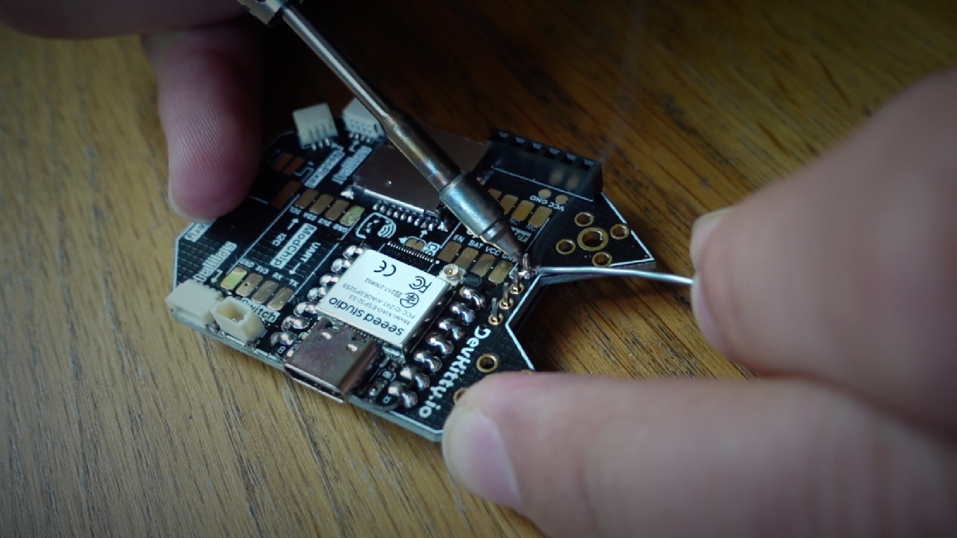
2. Solder the ESP32
Be extra careful not to burn the switch connector, or bridge neighboring pins.
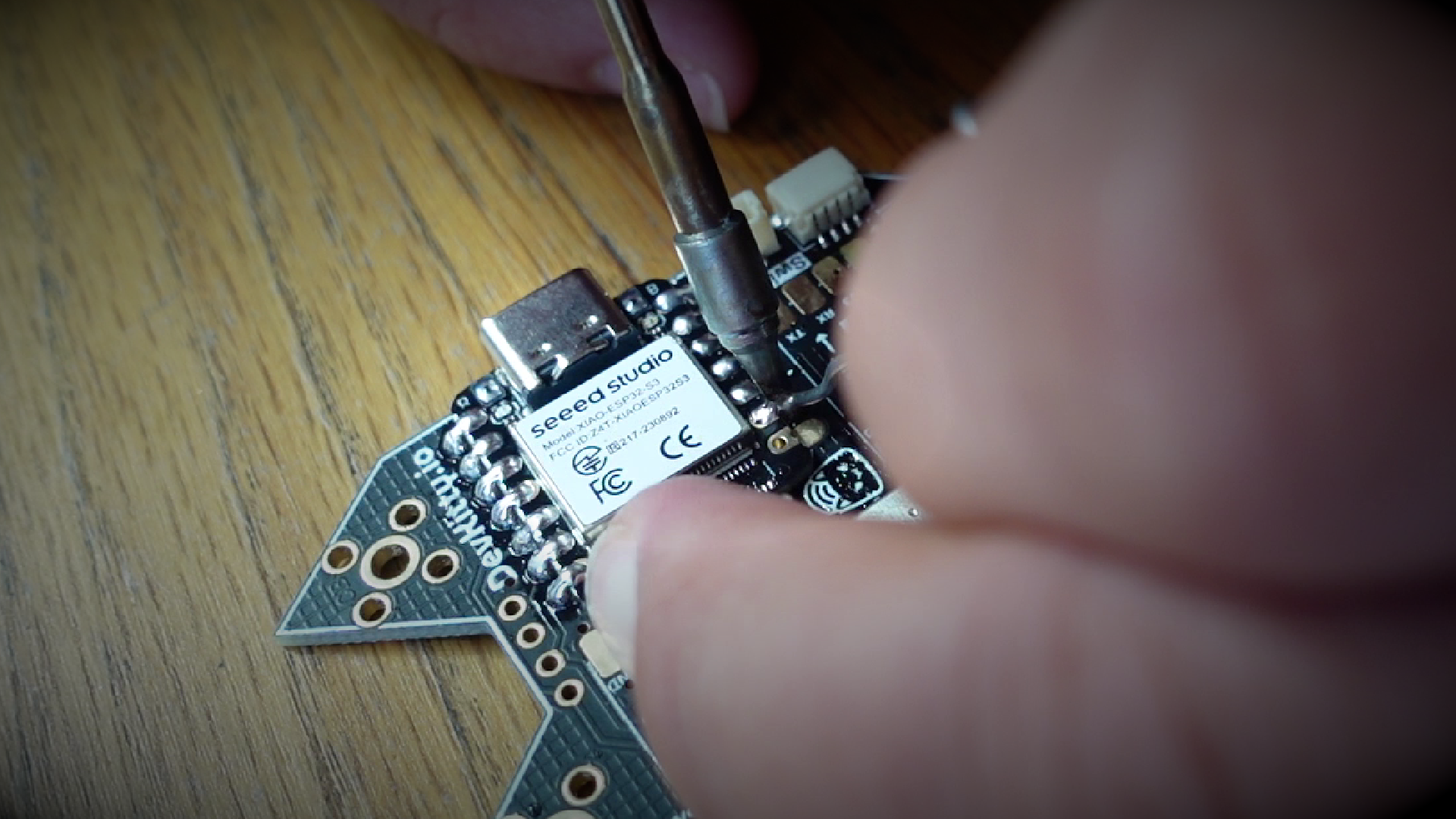
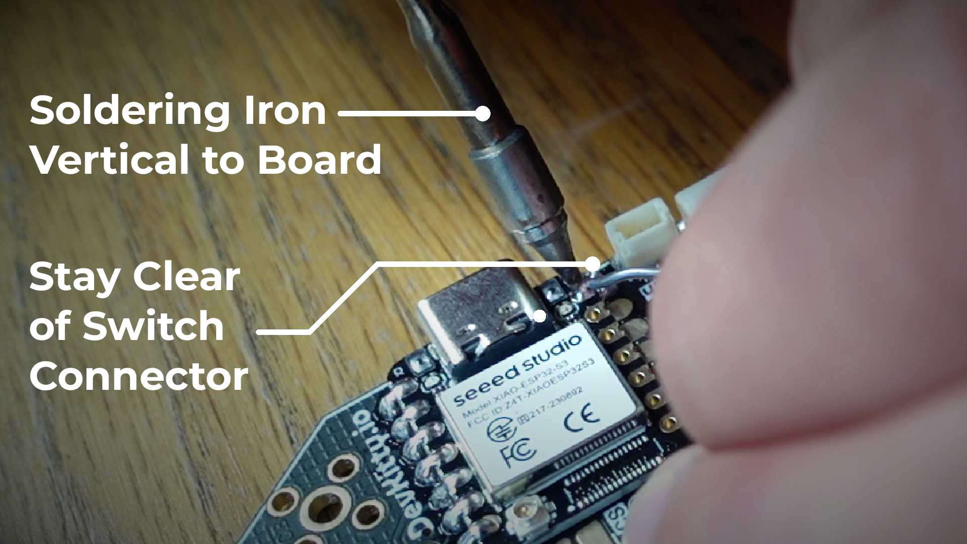
Solder the rest of the pins!
- a. Solder each remaining pad on the microcontroller!
- b. Ensure the connection is solid by bridging the ESP32 pad & PCB pads
- c. Avoid burning the switch connector! *
*Switch connector will be moved in update v0.1 design
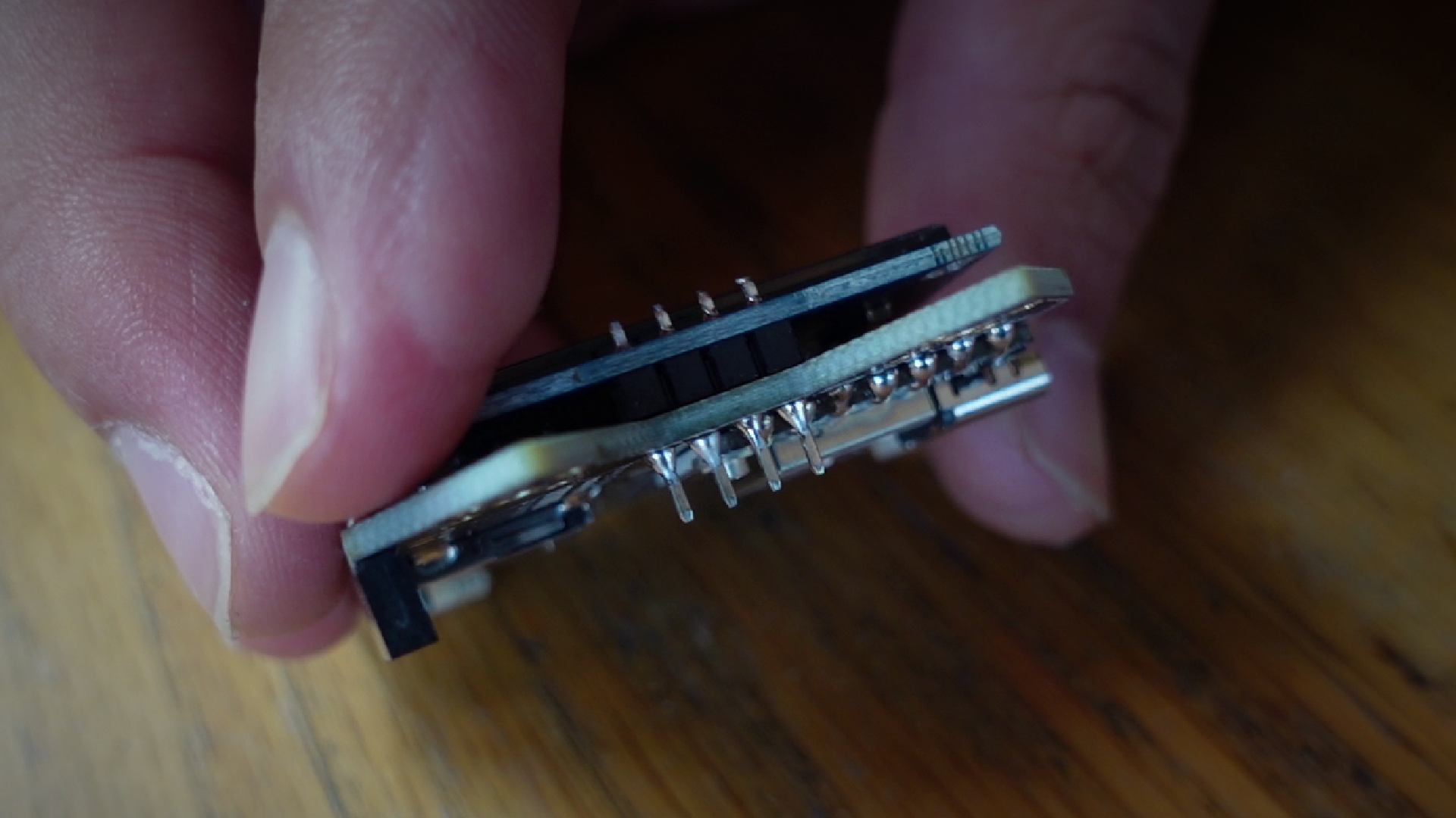
3. Solder the Expansion Header
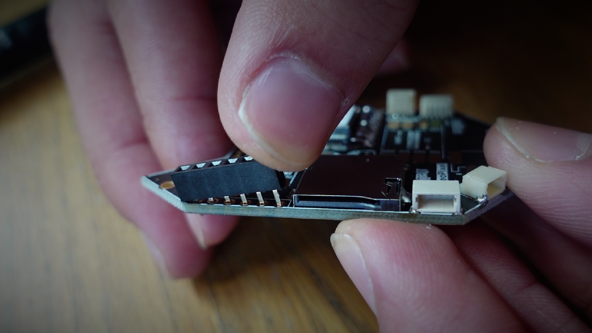
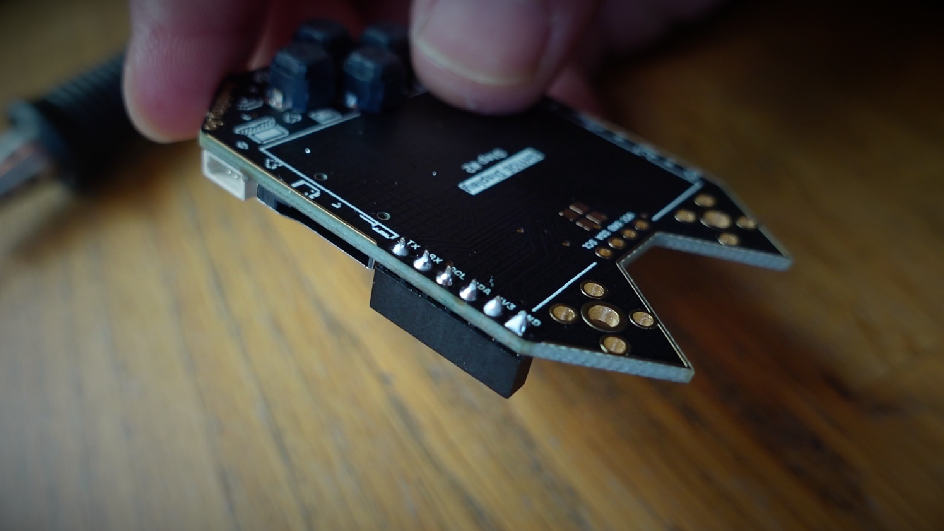
- a. Insert the 6-Pin Header on the Side
- b. Lay the board & header flush on a flat surface
- c. Solder the joints!
4. Prep + Solder the Screen
Press down on center of screen - the edges are really fragile!
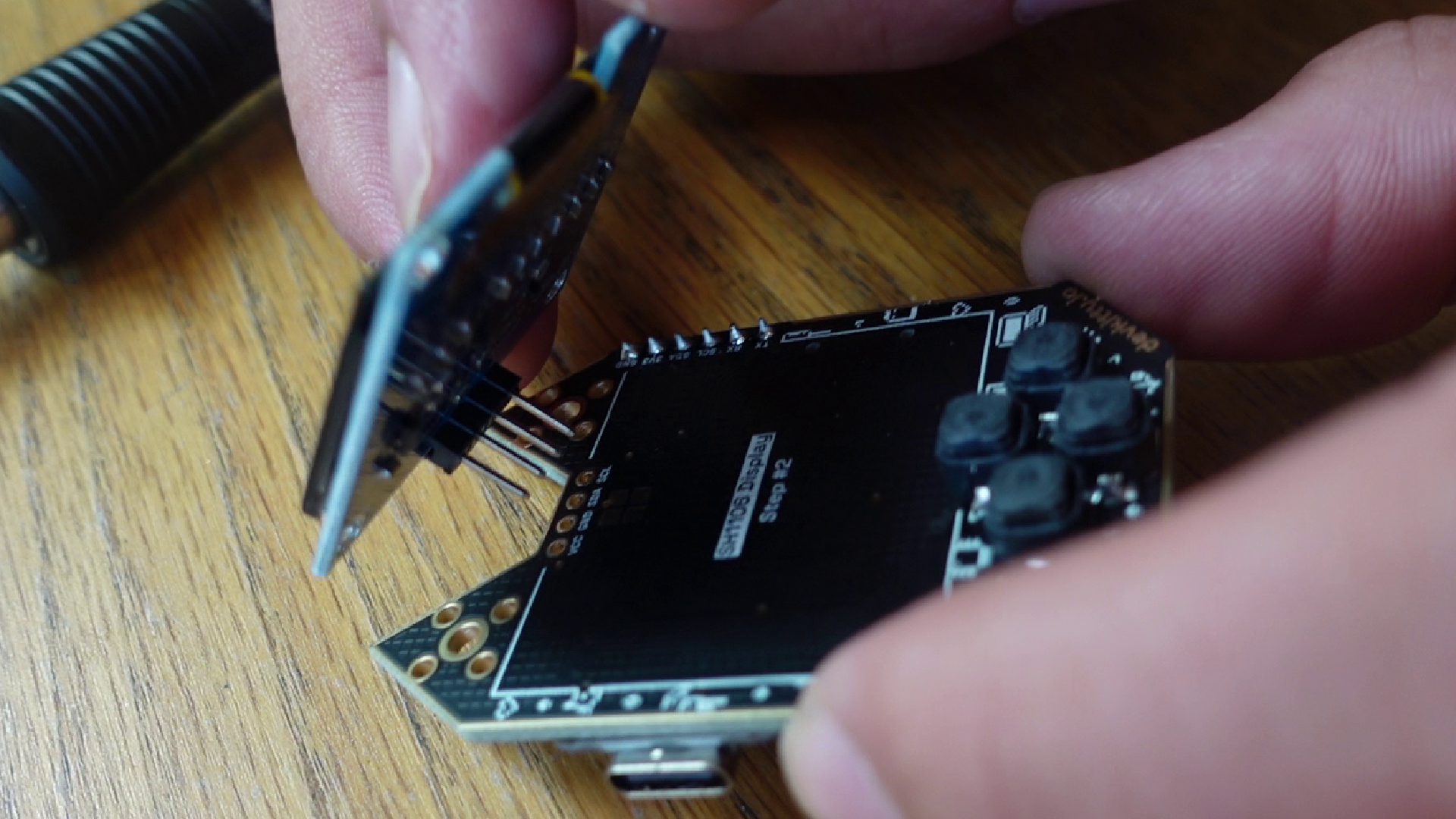
- a. Add double-sided foam tape at the bottom of the screen footprint (not pictured)
- b. Center & press the screen in place.
- c. Solder the screen joints on the back.
5. Antenna & Case Assembly
Read our long-range mod guide before adding the external antenna!!
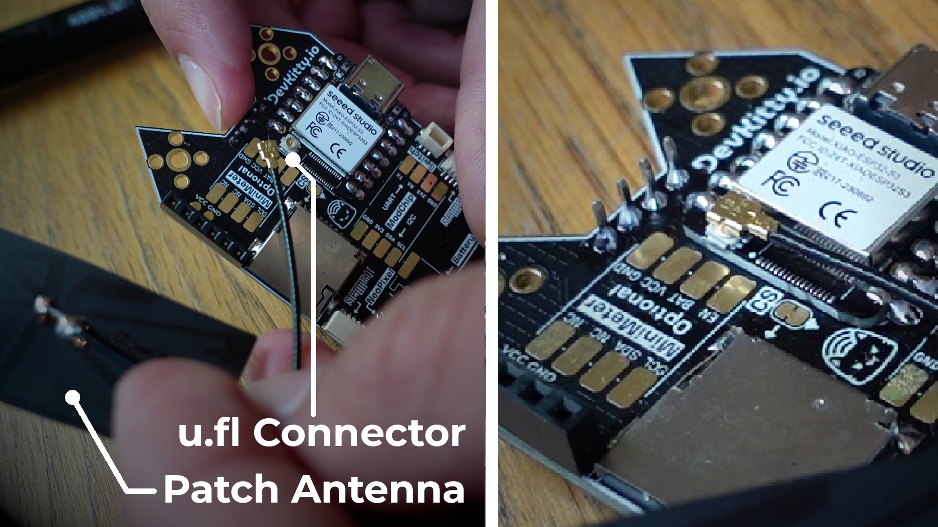
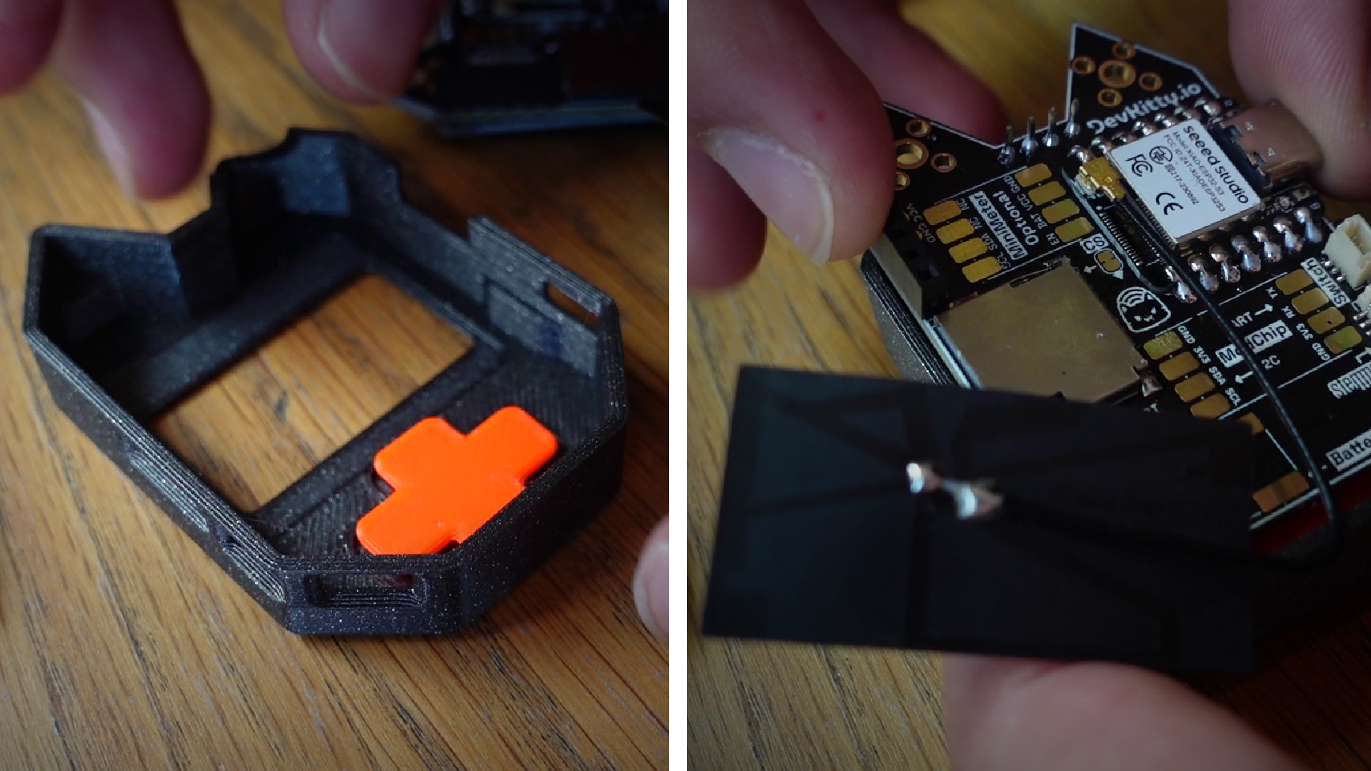
- a. Snap the patch antenna onto the ESP32 u.fl connector
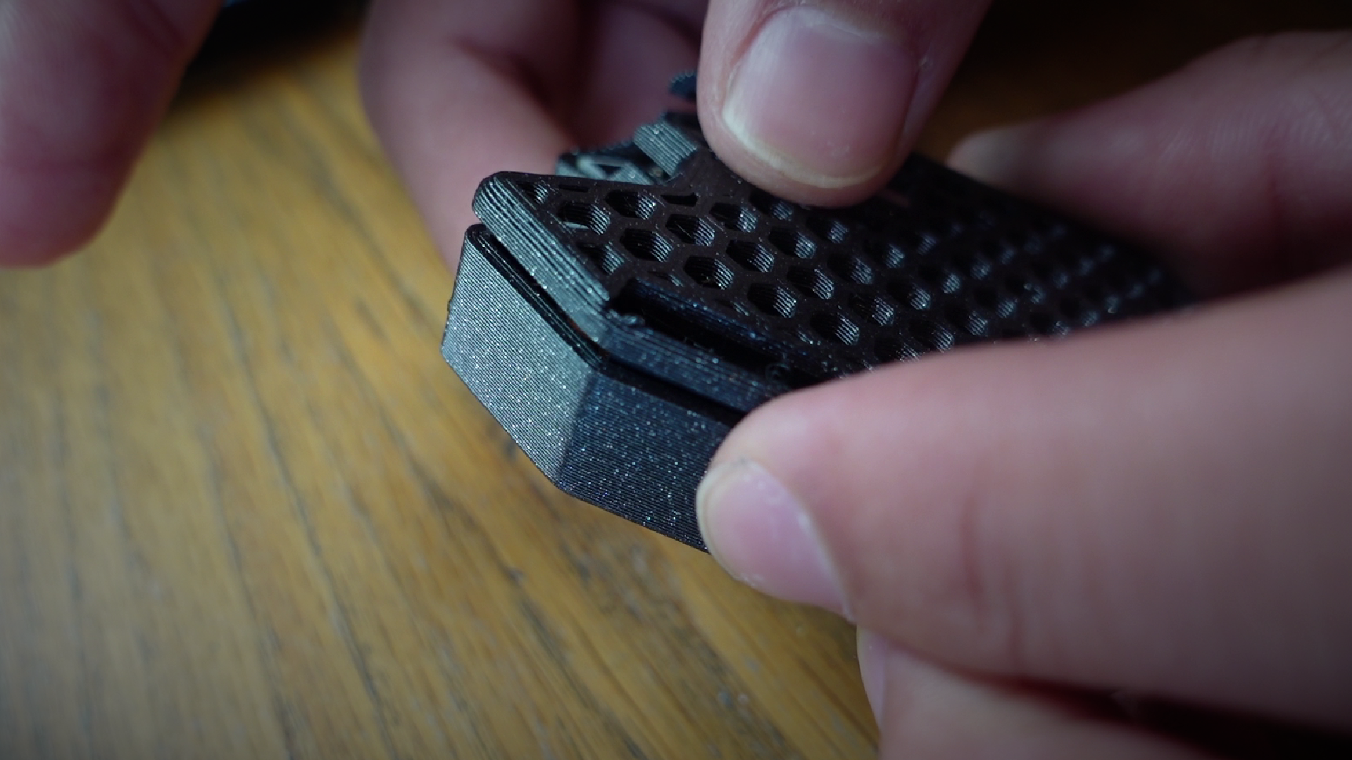
- b. Insert the D-Pad into the Top Enclosure
- c. Place the CutieCat in face-down
- d. Snap-on the Back Enclosure!
6. Quality Assurance
- Plug in your CutieCat with USB Type C
- With your board fully assembled, it should power on the QA Firmware!
- Check out our Firmware Guide to load new firmware.
If your board doesn't work, check our troubleshooting guide.
🔧 Additional Mods
Check out our mods section for more, including adding the long-range antenna!